This guide will cover a description of parylene, the parylene deposition process, and detailed descriptions of the properties and characteristics of parylene. Learn more about our company, facility, and capabilities here.
This application guide is provided to assist in the selection and application of Parylene Conformal Coating for a wide array of uses.
The data provided herein is of a general nature in order to accommodate the wide application variations encountered with this type of product.
Specific application criteria may already be available for your specific intended purpose. Typically, performance characteristics and application design can be easily obtained for variant uses through physical inspection and testing procedures accomplished by Advanced Coating.
For Technical Questions and/or to arrange an applications performance analysis contact the following:
Advanced Coating
Attn: Engineering Dept.
10723 Edison Court
Rancho Cucamonga, CA 91730
909-481-1400/Fax 909-481-1427
E-Mail: engr@advancedcoating.com

Parylene is a common generic name for a unique series of polymers based on paraxylene. The three most common Parylene types are Parylene N, Parylene C, and Parylene D.
In actual usage, Parylene C is the greatly predominant type of Parylene used for almost all types of applications and as such is usually the type of material associated as “Parylene.”
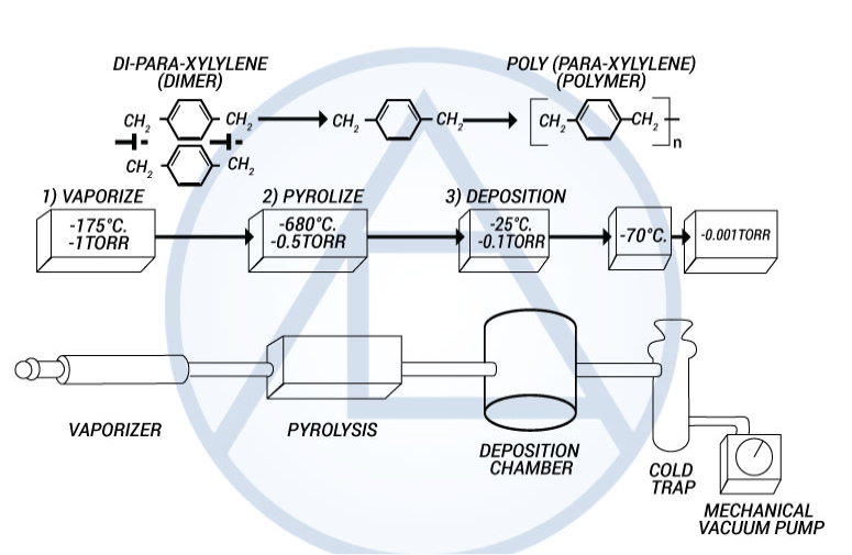
The basis for the Parylene family is the Poly -para-xylylene monomer which comprises Parylene N. Parylene C and D are created by the substitution of single chlorine molecule (C) or two [double] chlorine (D) (See Figure 1).
The Parylenes are formed by the pyrolisis of a di-para-xyxlene (dimer) in a vacuum environment which is then deposited on a cooler substrate (i.e., room temp.) under continuous vacuum.
Vapor phase deposition of the Parylene polymer allows it to be formed as a structurally continuous film that is truly conformal to the design and structure of the substrate for which it is being deposited on.
( See Figure 2 ).
Parylene can be effectively deposited with excellent accuracy in the thickness range of 0.1 Mils to over, 2 mils.
The parylene polymers are deposited from the vapor phase by a process that in some respects resembles vacuum metalizing. Unlike vacuum metallization, however, which is conducted at pressures of 10-5 torr or below, the parylenes are formed at around 0.1 torr. Under these conditions the mean free path of the gas molecules in the deposition chamber is in the order of 0.1 cm, therefore, unlike vacuum metalizing, the deposition is not line-of-sight and all sides of an object to be encapsulated are uniformly impinged by the gaseous monomer. This is responsible for the truly conformal nature of the coating. The process consists of three distinct steps as shown in Figure 3.
Since Parylene is non-liquid, it does not pool, bridge or exhibit meniscus properties during application. No catalysts or solvents are involved, and no foreign substances are introduced that could contaminate coated specimens.
In contrast to Parylene, the thickness of liquid coatings is related to viscosity, working temperature/humidity, and application process (spray or dip) and can only be controlled to a tolerance of approximately +/- 50% of final thickness.
Parylene thickness is a function of the amount of vaporized dimer and chamber dwell time and can be controlled accurately to within +/- 5% of targeted thickness for most typical applications.
Figure 1. Parylene Molecules
The most widely used dimmer, providing a useful combination of properties, plus a very low permeability to moisture, chemicals, and other corrosive gasses.
Provides high dielectric strength and a dielectric constant that does not vary with changes in frequency. Best selection where greater coating protection is required.
Maintains its physical and electrical properties at higher temperatures.
Figure 2. Parylene Conformal Characteristics Vs. Conventional Coatings
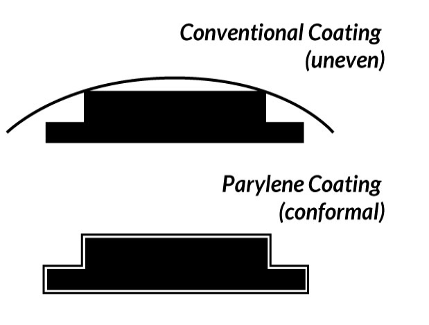
Figure 3. The Parylene Deposition Process
General properties and characteristics of Parylene are listed in Table 1.
Typical Specifications for Parylenes C, N & D are shown in Tables 2, 3 & 4 respectively.
|
Parylene C Value |
ASTM Method |
||
|
General |
|||
|
Density, g/cm3 |
1.289 |
D1505 |
|
|
Refractive IndexND23 |
1.639 |
||
|
ELECTRICAL |
|||
|
Dielectric Strength (Voltage Breakdown) Volts/mil |
5,600 volts |
D149 |
|
|
Dielectric Constant |
D150 |
||
|
60 Hz |
3.15 |
||
|
1kHz |
3.10 |
||
|
1 MHz |
2.95 |
||
|
Dissipation Factor |
D150 |
||
|
60 Hz |
0.020 |
||
|
1Hz |
0.019 |
||
|
1 MHz |
0.013 |
||
|
Dielectric Strength @ 25um, short time MV/m |
220 |
D149 |
|
|
Dielectric Strength @ 25um, step-by-step MV/m |
185 |
D149 |
|
|
Volume Resistivity @23 C, 50% RH, ohms |
8.8 x 10 16 |
D257 |
|
|
Surface Resistivity @23 C, 50% RH, ohms |
1 x 10 14 |
D257 |
|
|
MECHANICAL |
|||
|
Tensile Modulus GPa |
32 |
D882 |
|
|
Tensile Strength MPa |
70 |
D882 |
|
|
Tensile Strength psi |
10,000 |
D882 |
|
|
Yield Strength MPa |
5.5 |
D882 |
|
|
Elongation to Break, % |
200 |
D882 |
|
|
Coefficient of Friction-Static |
0.29 |
D1894 |
|
|
Coefficient of Friction-Dynamic |
0.29 |
D1894 |
|
|
Elongation to Break, % |
200 |
D882 |
|
|
Rockwell Hardness |
R80 |
D785 |
|
|
THERMAL |
|||
|
Melting Point, C |
290 C |
||
|
Linear Coefficient of Expansion (10-5/oC) |
3.5 |
D696 |
|
|
Thermal Conductivity @ 25oC (Watts/Meter-Kelvin) |
0.082 |
C177 |
|
|
Specific Heat @ 20o C cal/g/o C |
0.17 |
||
|
BARRIER |
|||
|
Water Absorption, % (24 hr) |
0.06 (.029”) |
D570 |
|
|
Water Vapor Transmission @ 37o C (ng) |
0.0004 |
D570 |
|
|
Gas Permeability cc-mil/100 in 2 - 24 hrs |
|||
|
N2 |
.6 |
||
|
O2 |
5 |
||
|
CO2 |
14 |
||
|
H2 |
110 |
||
|
Moisture Vapor Tranmission gm-mill/100 in - 24 hrs |
1 |
||
|
PARYLENE N VALUE |
ASTM METHOD |
||
|
General |
|||
|
Denisity, g/cm3 |
1.10 |
D1505 |
|
|
Regractive Index ND23 |
1.661 |
||
|
Electrical |
|||
|
Dielectric Constant |
D150 |
||
|
60 Hz |
2.65 |
||
|
1kHz |
2.65 |
||
|
1mHz |
2.65 |
||
|
Dissipation Factor |
D150 |
||
|
60 Hz |
0.0002 |
||
|
1kHz |
0.0002 |
||
|
1mHz |
0.0006 |
||
|
Dielectric Strength @ 25um, Short Time MV/m |
7000 |
D149 |
|
|
Dielectric Strength @ 25um, |
6000 |
D149 |
|
|
Volume Resistivity @ 23C, |
1.4x 10¹⁷ |
D257 |
|
|
Surface Resistivity @ 23C, |
1013 |
D257 |
|
|
Mechanical |
|||
|
Tensile Modulus CPa |
2.4 |
D882 |
|
|
Tensile Strength MPa |
43 |
D882 |
|
|
Tensile Strength psi |
6.500 |
D882 |
|
|
Yield Strength MPa |
43.4 |
D882 |
|
|
Elongation to Break, % |
40 |
D882 |
|
|
Yield Elongation, % |
2.5 |
D882 |
|
|
Coefficient of Friction-Static |
0.25 |
D1894 |
|
|
Coefficient of Friction-Dynamic |
0.25 |
D1894 |
|
|
Rockwell Hardness |
R85 |
D785 |
|
|
Thermal |
|||
|
Melting Point, o C |
405 C |
||
|
Linear Coefficient of Expansion (10-5/oC) |
69 |
D696 |
|
|
Thermal Conductivity @ 25o C (Watts/Meter-Kelvin) |
3 |
C177 |
|
|
Specific Heat @ 20oC cal/g/oC |
0.20 |
||
|
Barrier |
|||
|
Water Absorption, % (24 hr) |
.01 (.019”) |
D570 |
|
|
Water Vapor Transmission @ 27oC (ng) |
--- |
D570 |
|
|
Gas Permeability cc-mill/100 in2 - 24 hrs |
|||
|
N2 |
.6 |
||
|
O2 |
5 |
||
|
CO2 |
14 |
||
|
H2 |
110 |
||
|
Moisture Vapor Transmission gm--mil/100 in- 24 hrs |
1 |
||
|
Parylene D Value |
ASTM Method |
||
|
General |
|||
|
Denisity, g/cm3 |
1.4 |
D1505 |
|
|
Refactive Index ND23 |
1.669 |
||
|
Electrical |
|||
|
Dielectric Constant |
D150 |
||
|
60 Hz |
2.84 |
||
|
1kHz |
2.82 |
||
|
1 MHz |
2.80 |
||
|
Dissipation Factor |
|||
|
60 Hz |
0.004 |
||
|
1kHz |
0.003 |
||
|
1mHz |
0.002 |
||
|
Dielectric Strength @ 25um, short time MV/m |
--- |
D149 |
|
|
Dielectric Strength @ 25um, step-by-step MV/m |
--- |
D149 |
|
|
Volume Resistivity @23 C, 50% RH |
2 x 10 16 |
D257 |
|
|
Surface Resistivity @23 C, 50% RH, ohms |
5 x 10 16 |
D257 |
|
|
Mechanical |
|||
|
Tensile Modulus GPa |
2.8 |
D882 |
|
|
Tensile Strength MPa |
62 |
D882 |
|
|
Tensile Strength psi |
11,000 |
D882 |
|
|
Yield Strength MPa |
62 |
D882 |
|
|
Elongation to Break, % |
10 |
D882 |
|
|
Yield Elongation, % |
3.0 |
D882 |
|
|
Coefficient of Friction-Static |
0.33 |
D1894 |
|
|
Coefficient of Friction-Dynamic |
0.31 |
D1894 |
|
|
Rockwell Hardness |
--- |
D785 |
|
|
Thermal |
|||
|
Melting Point, C |
390 C |
||
|
Linear Coefficient of Expansion |
--- |
D696 |
|
|
Thermal Conductivity @ 25o C |
--- |
C177 |
|
|
Specific Heat @ 20oC cal/g/oC |
--- |
||
|
Barrier |
|||
|
Water Absorption , % (24 hr) @ 37oC (ng) |
--- |
D570 |
|
|
Gas Permeability cc-mil/100 in 2 - 24 hrs |
|||
|
N2 |
4.5 |
||
|
O2 |
32 |
||
|
CO2 |
13 |
||
|
H2 |
240 |
||
|
5 |
|||
|
Moisture Vapor Tranmission |
5 |
||
Thin Film Dielectric Properties
One of the features of parylene is that it can be formed in extremely thin layers. The DC breakdown voltage of parylene films has been determined as a function of polymer thickness, a plot of which is shown in Figure 4. Parylene C is superior to N in this respect for films under 5 microns (0.0002 inches). These data show that both parylenes have respectable dielectric withstanding voltages even below the 1-micron thickness range and the voltage breakdown per unit thickness generally increases with decreasing thickness.
Electrical properties of Parylene C compared to typical values of epoxies, silicones, and urethanes are shown in Table 5.
Insulation Resistance
A critical test of the protection afforded by the parylene coating is to coat circuit board test patterns (as described in MIL-I-46058) and subject them to insulation resistance measurements during a temperature-humidity cycle (MIL-STD-202, methods 106 and 302). In brief, this test consists of ten cycles (one cycle per day), each cycle being in seven steps. The seven steps range from low temperature, low humidity (25 oC, 50% RH) to more severe conditions (65o C, 90% RH). Resistance readings are taken initially and at periodic times at 65o C, 90% RH during the ten-day cycle.
Results are shown in Table 6 for Parylene C coatings 0.0001 inches to 0.002 inch in thickness. Even for the very thin coating (.0001 inch), the insulation resistance values are about one order of magnitude above the prescribed specification.
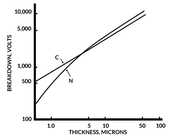
Figure 4. Breakdown Voltage of Parylene C & N Vs. Thickness
|
Properties (1) |
Method of Conditions |
Parylene C |
Expoxies |
Silicones |
Urethanes |
|
Dielectric Strength Volts/mil short time 1 mil films. |
ASTM D149-64 |
5,000 |
- |
- |
- |
|
corr. to 1/8” |
ASTM D149-64 |
590 |
400-500 |
550 |
450-500 |
|
Volume Resistivity, ohms 23o C, 50% RH |
ASTM D149-64 (1 in. 2 mercury electrodes ) |
8.8 x 10¹⁶ |
1012 - 1017 |
2 x 10¹⁵ |
2 X 10¹¹ - 1015 |
|
Dielectric Constant |
ASTM D160-65T |
||||
|
60 Hz |
(1 in. 2 mercury electrodes) |
3.15 |
3.5-5.0 |
7.75-3.05 |
4-7.5 |
|
103 Hz |
3.10 |
3.5-4.5 |
- |
4-7.5 |
|
|
106 Hz |
2.95 |
3.3-4.0 |
2.6-2.7 |
6.5-7.1 |
|
|
Dissipation factor |
ASTM D150-65T |
||||
|
60 Hz |
(1 in. 2 mercury electrodes) |
0.020 |
.002-.01 |
.007-.001 |
.015-.017 |
|
103 Hz |
0.019 |
.002-.02 |
- |
.05-.06 |
|
|
106 Hz |
0.013 |
.03-.05 |
.001-.002 |
- |
(1) Properties measured on parylene films, 0.001 inches thick.
[ (Ohms) MIL-STD 202 Method 302]
|
Parylene C Thickness, (inches) |
Measurement Temp. 23oC |
Precycle Temp 23oC RH90% |
Step 5 Cycle 3 Temp 65oC RH90% |
Step 5 Cycle 7 Temp 65oC RH90% |
Step 5 Cycle 10 Temp 65oC RH90% |
Step 7 Cycle 10 Temp 25oC RH90% |
|
0.002 |
2.0 X 10¹⁴ |
1.8 X 10¹³ |
2.3 X 10¹² |
2.5 X 10¹¹ |
1.4 X 10¹¹ |
7.5 X 10¹² |
|
0.0015 |
5.0 X10¹⁴ |
2.4 X 10¹³ |
.6 X 1011 |
1.9 X 10¹¹ |
1.1 X 10¹¹ |
5.2 X 10¹² |
|
0.001 |
2.0 X10¹⁴ |
9.2 X10¹² |
8.1 X 10¹¹ |
3.4 X 10¹¹ |
1.3 X 10¹¹ |
6.3 X10¹² |
|
0.0005 |
5.0 X10¹⁴ |
2.3 X 10¹³ |
4.1 X 10¹² |
2.4 X 10¹¹ |
1.1 X 10¹¹ |
4.7 X 10¹² |
|
0.0003 |
5.0 X10¹⁴ |
2.7 X10¹³ |
4.4 X 10¹² |
9.0 X 10 10 |
4.7 X 10 10 |
2.9 X 10¹² |
|
0.0001 |
5.0 X10¹⁴ |
3.2 X 10¹⁰ |
1.3 X 10¹¹ |
1.1 X 10¹¹ |
6.4 X 10¹⁰ |
2.3 X 10¹² |
Physical and Mechanical Properties
Physical and mechanical properties of the parylenes are summarized in Tables 2 - 4.
Table 7 shows a comparison of physical and mechanical properties of Parylene versus typical values of Epoxies, Silicones, and Urethanes.
Because of their high molecular weight (~ 500,000) and because the melting temperatures and crystallinity are high, the parylenes cannot be formed by conventional methods such as extrusion or molding. Solubility in organic or other media, except at temperatures above 175o C, is so low that they cannot be formed by casting.
Impact resistance is high when the parylene polymers are supported on test panels. Gardiner falling ball impact tests on 0.001 inches thick parylene C coated steel “Q” panels are in the 250 inch-pound range.
Wear index values (measured on a Tabor Abraser machine using CS-17 Calibraser wheels and 1000 gram weights) were 22.5 for parylene C and 8.8 for parylene N. By comparison, “Teflon” is 8.4, high impact PVC is 24.4, epoxy is 41.9 and urethane is 59.5.
Parylenes may be annealed to increase cut-through resistance, increase hardness and improve abrasion resistance. This is the result of a density and crystallinity increase.
|
Properties (1) |
Method or Condition |
Parylene C |
Epoxies |
Silicones |
Urethanes |
|
Secant Modulus, psi |
ASTM D882-56T @ 1% Strain |
400,000 |
350,000 |
900 |
1,000 - 10,000 |
|
Tensile Strength, psi |
ASTM D882-56T @ |
10,000 |
4000 - 13,000 |
800 - 1000 |
175 - 10,000 |
|
Yield Strength , psi |
ASTM D882-56T @ |
8,000 |
- |
- |
- |
|
Elongation to Break , % |
ASTM D882-56T @ |
200 |
3-6 |
100 |
100 - 1,000 |
|
Yield Elongation, % |
ASTM D882-56T @ |
2.9 |
- |
- |
- |
|
Density , gm. / cc. |
ASTM D1505-57T |
1.289 |
1.11-1.40 |
1.05-1.23 |
1.10-2.5 |
|
Index of Refraction nd23 |
Abbe Refractometer |
1.639 |
1.55-1.61 |
1.43 |
1.50-1.60 |
|
Water Absorption, 24 hr |
ASTM D570-57T |
.06 10029”) |
.08-1.5 |
.12(7 days) |
.02-1.5 |
|
Rockwell Hardness |
ASTM D785-65 |
R80 |
M80-M110 |
40-50 |
10A-25D |
|
Coef. of Friction |
ASTM D1894-63 |
||||
|
Static |
.29 |
||||
|
Dynamic |
.29 |
(1) Properties measured on parylene films, 0.001-0.003 inch thick, except where specified.
(2) Properties dependent on deposition conditions.
Coatings are used on circuit boards to provide protection from hostile environments, fungus, shorting and arcing. A stringent test of the ability of the coating to protect the board and its components is the military specification, MIL-I-46058, which qualifies a limited number of epoxy and urethane materials at specified thickness’. These thicknesses’, for sprayed and/or dipped coatings, are measured on flat surfaces and in reality, might have little bearing as to what the actual coating coverage is on the most critical areas of the board; edges, corners, depression walls, and points.
This section describes a technique and the results for measuring the amount of mechanical properties one can expect from various coatings and their methods of application when applied to a critical area of a circuit board, a sharp point. A comparison is made between the vapor deposited parylene C, a multiple dipped epoxy, and a sprayed urethane.
By comparison of abrasion results acquired with these materials and by photomicrograph comparison of the coverages obtained, it is demonstrated that a 2.5 um coating of parylene C will afford the same protection as will an epoxy or urethane coating at more than ten times this thickness.
Several standard methods for estimating the mechanical protective ability (handleability) of a conformal coating material exist, among them being Tabor Abrasion drop tests, cut-through tests, puncture tests, Sward hardness, etc. None of them, however, specifically relate the particular material property to its performance when applied to the circuit board. Therefore, a method was devised to measure the abrasion of the conformal coating at the most critical area of the circuit board, on a sharp point. For test standardization purposes, a metal phonograph needle was used to simulate a typical sharp point.
An abrasion testing apparatus was assembled which resembles a phonograph. The turntable portion maintains constant speed under a wide variety of load conditions and is fabricated from chromium plated brass. The arm is electrically insulated from the turntable and holds the needle being tested; it is counterbalanced by a weight on the opposite side of the fulcrum. A table above the needle is used to apply a known load to the 60um radius point.
A continuity meter is attached between the needle and turntable; this meter automatically turned off the apparatus when continuity between the two was established. Since the coatings tested are dielectrics, ohmic contact would occur only when the coating was worn away (thereby exposing the metal needle tip) by the rotating turntable. At this point, failure is indicated and the turntable revolutions and time to failure were recorded.
The needles were coated with either Parylene C, Epoxy (dip coat) or Urethane (sprayed).
The epoxy was applied to a set of needles attached to the periphery of a cork by dipping as a set into the liquid. The needles were removed to cure with the points facing up. Two sets of epoxy-coated needles were evaluated; one set using three such dip and cure steps and the second set using four. Sets evaluated with only one or two epoxy applications indicated no coating on the point (as evidenced by ohmic continuity between the needle and turntable), although a build-up of epoxy nearly 3mm in diameter had accumulated at the base of the needle.
Additional attempts to obtain an epoxy-coated point by other means were also made. The needles were (a) coated and cured points down, (b) coated and cured in a silicone mold, and (c) in a continuous dipping and curing cycle with the needle held at 45o to the horizontal (point down). The first two methods were completely unsuccessful (no coating at the point), the third did coat the point but required such a mass of epoxy as to make the method untenable.
The urethane was applied in several spray cycles. The needles, set in a rubber cork, were rotated during the spray operation. The procedure was to use two wet passes, a cure cycle, two additional wet passes, and a second cure cycle. The thickness of the urethane on a flat surface coated concurrently was 90-100 microns. (≈ 4 Mils) However, as indicated by continuity testing and micro-graphic cross-sectioning, the tip of the needle was bare. No further attempt to obtain a coating on the needle was made because of the extremely large amount of material that would have to have been deposited on the concurrently coated flat surface.
The coating thickness was determined by potting and cross-sectioning the needles and then measuring the thickness on a calibrated micrograph. For the parylene-coated needles, the substrates were sectioned perpendicular to the long axis of the needle. Since the coating is uniform, the point of sectioning was relatively immaterial. Three points were randomly selected from each cross-section and three needles were used (nine points total ).
Obtaining the thickness of the epoxy on the needles was more difficult because of the extreme non-uniformity of the coating; i.e., the coating at the point was much thinner than the coating further away from the point. For example, it was found in one instance that for a needle that had an epoxy thickness of 8.6 um at the tip, the epoxy thickness just 1mm away from the tip was 108 um.
For this reason, the epoxy needles had to be sectioned parallel to the long axis of the needle, a very tedious and delicate task. The thickness of the epoxy was then measured as cited above for parylene.
This disparity of coverage uniformity for sprayed/dipped coatings is not peculiar to the tip of a needle. Circuit boards have several areas which will not receive an even coating of applied protective material; the corner or edge of an object, the space between two closely spaced components, the walls of a hole, etc. A good illustration is the edge of the Y shaped conductor pattern which is used as the test vehicle for MIL-I-46058. A cross-section of such a pattern shows where the epoxy material is shown to be non-uniform in coverage at the copper conductor edges and between the two conductors whereas the thickness of the parylene is the same on all surfaces.
The rate of abrasion of a coating will be a function of (a) the force applied to the coated object and (b) the surface area presented. Logically, the greater the force causing abrasion, the faster will be the rate of wear. Also, the smaller the area being abraded, the faster the rate of wear (constant load conditions).
If “W” is the weight of coating removed in distance “X” by the application of a load, “F”, then
|
W = kFX |
(1) |
where “k” is a constant. The weight removed can be related to the volume removed by the material density (p) and in turn, the volume is relatable to the area presented (A) and the thickness removed (y).
Substituting for the “W” and differentiating leads to
|
(2) |
dx= |
pA |
dy= |
A dy |
where “k” is being defined as the “wear index”.
In the case of a needle abraded in the vertical position, it can easily be shown that the area presented at any time is
|
A =2~πRY + 2~rty - ~ry2 |
(3) |
where “R” is the radius of curvature of the needle tip and “t” is the total thickness of the conformal coating.
Equation (3) can be substituted into Equation (2), which upon integration yields:
|
X= |
T |
(4) |
From Equation (4 ) it can be seen that when the coating thickness is insignificant compared to the radius of curvature, the time to abrade varies with the square of the coating thickness. When the coating thickness is large in comparison to the radius of curvature, the abrasion time increases with the cube of the coating thickness. In any instance, for a constant coating thickness, the abrasion time is inversely proportional to the force applied to the point.
The validity of Equation (4) was tested by plotting the distance to failure against (1) the thickness function and (2) the reciprocal force. Figure 5 shows the former at a constant load of 5.0 grams for parylene thickness’ of 3.3 um to 38.3 um and for epoxy thickness’ of 8.6 um and 22.4 um. These thickness’ were those measured at the needle tip as previously described. The two lines are parallel but have a slope slightly higher than unity because the needles were abraded somewhat off the vertical position.
As previously stated, at constant thickness, the distance to failure should vary inversely with the force applied (F). The data is plotted in Figure 6 showing this to be the case. Both constant thickness lines extrapolate to the origin indicating to time to failure would be instantaneous at an infinite loading (which is not quite true as there is a finite load which would puncture the film).
Where T = π + 2 (Rt 2/3 t) and is defined as the “thickness function”.
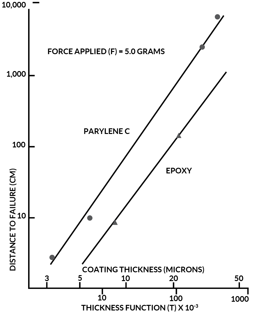
Figure 5. Parylene C Wear Index Vs. Epoxy
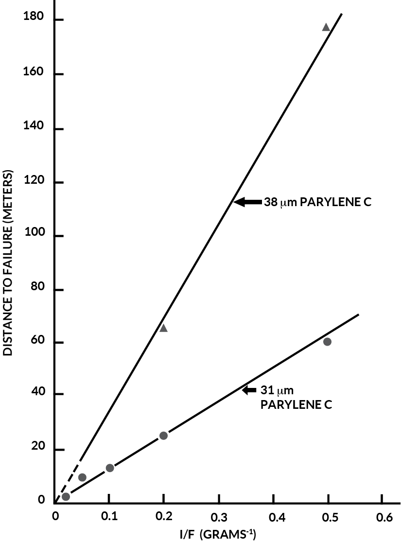
Figure 6. Comparison of Parylene Wear Index at Two Different Thickness
From Figure 5, the wear index, k, can be calculated as follows:
|
Parylene C |
29.7 |
|
Epoxy |
206 |
These values are valid when the force applied is expressed in grams, the coating thickness is in microns and the distance to failure is in centimeters. Therefore, in the thickness level range tested, at the equal thickness and equal force, the parylene C is about seven times more wear resistant than is the epoxy.
It would be useful to translate these results into a meaningful comparison. For example, how far can one abrade a circuit board along a hard surface before the coating will wear through and expose the metal tip of a clinched wire.
Let us assume that a typical circuit board, with all components, weighs 60 grams. Each feedthrough connecting the wire on the board measures 0.5mm diameter, thus the minimum radius of curvature of a clinched point would be R = 0.25mm. The minimum contact of the board, when set onto a flat surface, would be three points, therefore, each point would support 1/3 of the weight or 20 grams. Figure 7 relates the distance this board may be moved with various parylene and epoxy thickness’ using the above data and the values of “k”, the wear indices, found in this study.
From Figure 7, one can see that parylene coated boards can be moved much farther than the epoxy at equivalent thickness’. For example, at 25 microns, the parylene C coated board may be abraded through a distance of almost 9 meters before the clinched metal wire is exposed; the epoxy at 25 microns would be able to travel only 1.2 meters before failure.
MIL-I-46058 qualifies epoxy systems from a minimum of 25microns to a maximum of 75 microns ( 0.002 +/- 0.001 inch ).
This, of course, assumes that when the circuit board is coated with epoxy, the points will be coated to the same thickness’ as the flat land areas. As evidenced by photomicrographs and by the experience with the urethane, this is hardly the case. In fact, from the micrograph, it would be safe to assume that there is a minimum of a 10:1 disparity between the point thickness and the thickness at a very small distance from the point (<lmm). If these criteria were used, then the maximum allowable 75-micron epoxy coating would produce no more than a 7.5.micron coating on the points in question. From Figure 7, the abrasion resistance of 2.5 microns of parylene C would be equivalent to 7.5 microns of epoxy on the point or 75 microns of epoxy on a flat surface.
The ability of a conformal coating to protect a circuit board from hostile chemical, biological and mechanically damaging environments will depend upon the coverage which can be obtained with the coating as well as its inherent protective properties. It has been demonstrated in this article that the spraying or dipping of epoxy and urethane systems leave the most critical areas of the circuit board with the least amount of protection. The vapor deposited parylene C, however, is shown to afford an equivalent amount of mechanical protection at less than one-tenth the thickness of a dip-coated epoxy because of its superior coverage and thin film abrasion.
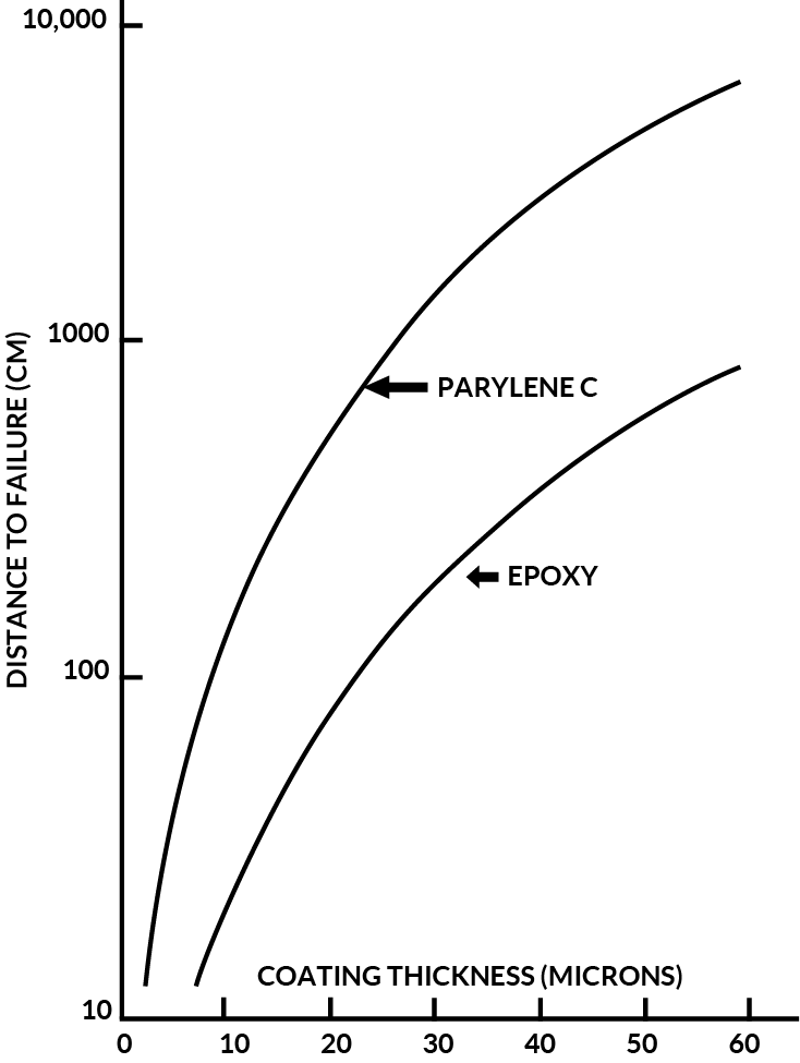
Figure 8 shows a comparison of Parylene C, Epoxy and Polyurethane hardness as measured using the “ Sward “ scale.
Table 8 lists the standard “ Taber “ wear index for both parylene C and N in relation to
Urethane and Epoxy. Table 9 Lists “ Pencil Hardness “ for Parylene C, Urethane and Epoxy and Table 10 compares impact resistance for these same materials.
By analysis of this data, it is evident that Parylene C provides superior mechanical protection at thickness’ utilized for conformal coating applications.
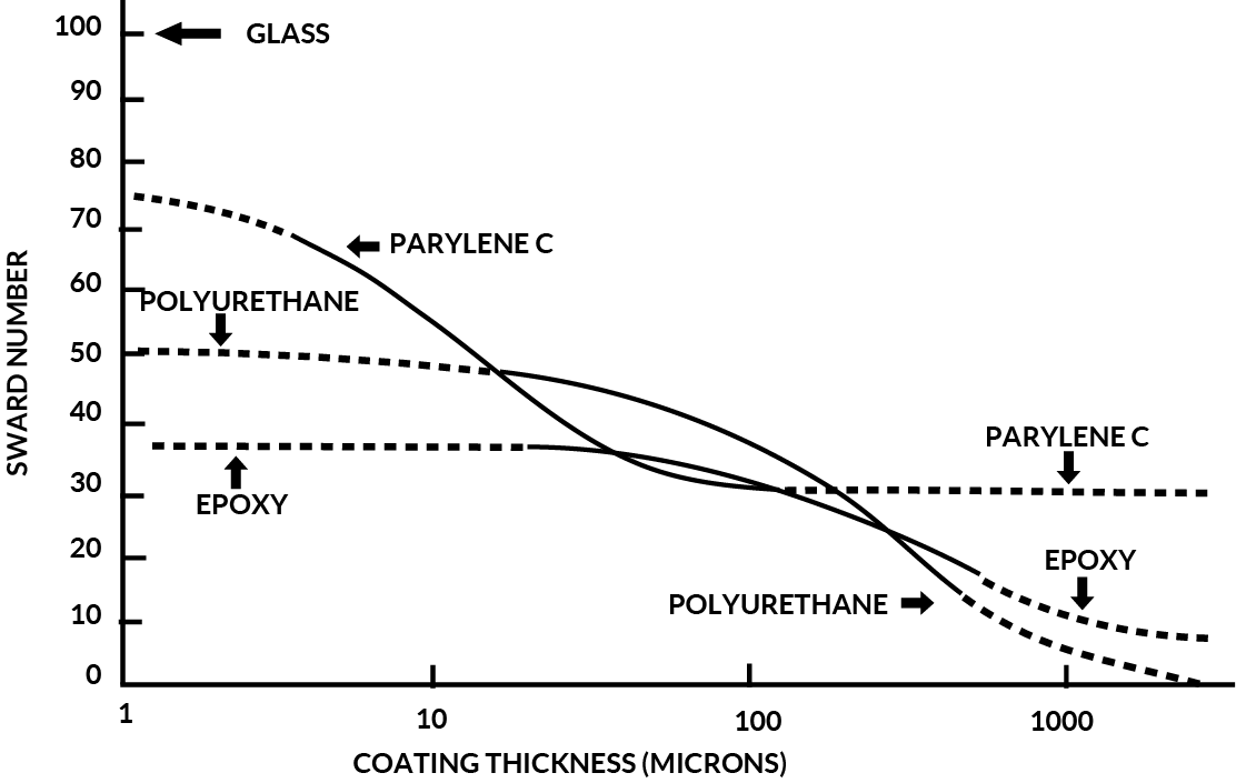
Figure 8. Parylene C Hardness Vs. Polyurethane and Epoxy (Sward Number)
|
0.97 |
.005 - .0075 |
Thickness (cm) |
|
Parylene N |
- |
9 |
|
Parylene C |
- |
29 |
|
Urethane |
23 + 2 |
60 |
|
Epoxy |
30 + 10 |
42 |
|
Material |
Pencil Hardness |
|
Parylene C |
2H |
|
Urethane |
3H |
|
Epoxy |
4H |
|
Material |
Thickness (Microns) |
Impact Resistance (Kg-cm) |
|
Parylene C |
||
|
3 |
>85 |
|
|
5 |
>85 |
|
|
8 |
>85 |
|
|
16 |
>85 |
|
|
30 |
>85 |
|
|
50 |
>85 |
|
|
73 |
>85 |
|
|
Urethane |
||
|
25 |
23 |
|
|
63 |
25 |
|
|
125 |
51 |
|
|
250 |
74 |
|
|
375 |
>85 |
|
|
Epoxy |
||
|
125 |
35 |
|
|
250 |
81 |
|
|
375 |
>85 |
The coefficients of thermal expansion of the parylenes are similar to epoxies: approximately 35 ppm/degrees C vs 27 to 30 ppm/degrees C for most epoxy molding compounds.
Based on extrapolation of test data, Parylene C is expected to survive continuous exposure to air at 100 degrees C for ten years (100,000 hr.). In oxygen-free atmospheres, it is expected to survive the period at 220 degrees C.
Table 11 illustrates parylene thermal characteristics as compared with epoxies, silicones, and urethanes.
In general, Parylene is capable of withstanding exposure to cryogenic temperatures. Steel panels coated with Parylene C and chilled in liquid nitrogen at -160 oC have withstood impacts of more than 100 inch-lb. in a modified Gardiner falling ball impact test. This compares with values of approximately 250 in-lb. at room temperature.
Unsupported films of Parylene C 0.002” thick can be flexed 180 degrees six times at -165o C before failure occurs. Comparable films of polyethelene and “ Teflon “ fail at three and one flex respectively.
Neither electrical nor physical properties are affected by temperature cycling from -271o C to room temperature.
Vacuum tests conducted by the Jet Propulsion Laboratory showed a total weight loss of 0.12% for Parylene C at 121 degrees F and 10-6 torr. Collectible volatile, condensable material values were less than 0.01% (the sensitivity limits of the test).
The thermal endurance in the air of Parylenes N, C and D have been measured using an induction time-to-initial weight-loss method. Based on an Arrhenius extrapolation of these data, the temperature for 100,000 hours’ endurance is 106oC in the case of Parylenes N and C, and 134oC in the case of Parylene D.
In inert atmospheres, the temperature for 100,000 hours endurance is greater than 200oC for all three Parylenes.
All plastics undergo degradation at rates which increase with temperature; the higher the use temperature the shorter the time a plastic will perform the desired function.
From the viewpoint of design, a frequent concern is how long a structure will function under a given set of thermal conditions. Design criteria may specify minimum lifetimes at specific temperatures. Only aging test on the total structure will answer completely whether a lifetime criterion is met. However, since the properties of a structure’s components will usually combine to give the properties of the total structure, it is generally possible to estimate the limitations on structure lifetime imposed by a specific component.
|
Properties (1) Urethanes |
Method or Condition |
Parylene C |
Epoxies |
Silcone |
|
|
T (melting), o C |
Taken from secant modulus - temperature curve |
280 |
Cured |
Cured |
~170 |
|
T (glass transition), o C |
Taken from secant modulus - temperature curve |
80-100 |
120 |
-130 |
-10 |
|
T (where modulus = 105),o C |
Taken from secant modulus - temperature curve |
125 |
110 |
-125 |
-30 |
|
T (where modulus = 104), o C |
Taken from secant modulus - temperature curve |
240 |
120 |
-80 |
0 |
|
Linear Coef. of Expansion ( 10 -5/oC ) |
ASTM D696 - 44 (61) |
-3.5 |
4.5 - 6.5 |
25 - 30 |
10 - 20 |
|
Specific Heat @ 20 o C cal / g / o C |
- |
0.17 |
.25 |
- |
.42 |
Often it is necessary to rely on accelerated aging tests in estimating component lifetimes, This is especially true with advanced materials for which experience on extended thermal endurance is not available. The useful lifetime of a coating may be affected by factors other than the material of which it is made. Its thickness, the material the coating contacts; the presence of oxygen; and in particular the criterion used to determine the end of useful life.
While a single set of conditions cannot universally describe all situations, the component or material supplier can offer the best available thermal aging data on his product. The purpose of this section is to present these data on the Parylenes, along with sufficient explanation to make them useful in design predictions.
Samples of Parylenes N, C and D were held at constant elevated temperatures in an air atmosphere. Characteristically, they remained at a nearly constant weight for a period of time (the induction period) before starting to steadily lose weight. Sometimes, for Parylene C, this period was marked by a 1/2% increase in weight. An explanation of this phenomenon is that oxidation is present from the outset but does not immediately result in formation of volatile products. The length of the induction period at a particular temperature was chosen as the useful life criterion.
The data were treated by a least squares procedure. A common Y-axis intercept was postulated, equivalent to assuming identical entropies of activation for the three Parylenes. Extrapolations are given in Figure 9. To the extent that the induction period is a predictor of properties, the extrapolations show Parylenes N and C to be statistically equivalent in thermal endurance (100,000 hours at 106oC) while Parylene D is significantly better (100,000 hours at 134oC).
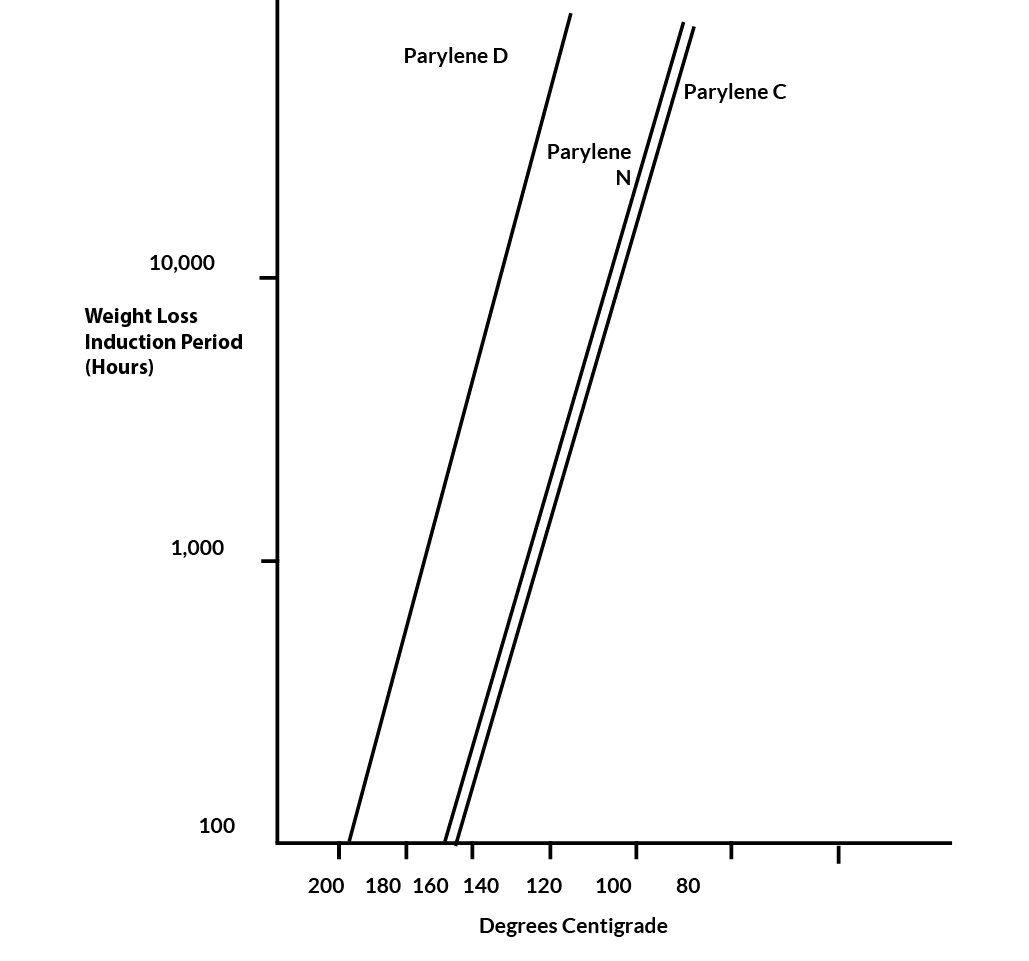
Figure 9. Thermal Endurance of Parylene C, N & D in Air Atmosphere
Due to the physical properties of Parylene and the method of deposition, Parylene forms a pinhole-free film on the subject substrate. Therefore, it provides an excellent barrier to both liquids and gases. Table 12 lists the permeability characteristics of the Parylenes and also shows typical values for other types of conformal coatings.
Moisture vapor permeability values have been measured at thickness’ below 0.1 microns.
Normalized to equivalent thickness, the values are the same for all thickness’. Assuming that parylene C at 0.001 inches is pinhole free, then parylene C films at 0.1 micron (~ x 10-6 inch) are also pinhole free.
TABLE 1 2- Barrier Properties of Parylenes C and N Compared with epoxies, silicones, and urethanes
|
Gas Permeability |
|||||
|
Transmission Polymer |
N2 |
O2 |
Co2 |
H2 |
Moisture Vapor Gm-mil/100 In. - 24 Hours ** |
|
Parylene C |
.6 |
5 |
14 |
110 |
1 |
|
Expoxies |
4 |
5-10 |
8 |
110 |
1.79 - 2.38 |
|
Silicones |
- |
50,000 |
300,000 |
45,000 |
4.4 - 7.9 |
|
Urethanes |
80 |
200 |
3,000 |
- |
2.4 - 8.7 |
* ASTM D 1434 - 63T
** ASTM E96 - 63T
Parylene exhibits very little absorption in the visible region and is, therefore, transparent and colorless.
Below about 280 mu both N and C absorb strongly as shown in Figure 10.
Both parylenes are relatively featureless to at least 50-micron wavelengths (except for a few characteristic peaks), especially in thin film form (<1u). The IR spectra for 1 mil films are shown in Figures 11 and 12.
Parylene C and N films show a high degree of resistance to degradation by gamma rays in a vacuum. Tensile and electrical properties were unchanged after 100 megarad dosage at a rate of 1.6 megarads per hour. Exposure to air leads to rapid embrittlement.
Although stable indoors, the parylenes are not recommended for use outdoors when exposed to direct sunlight.
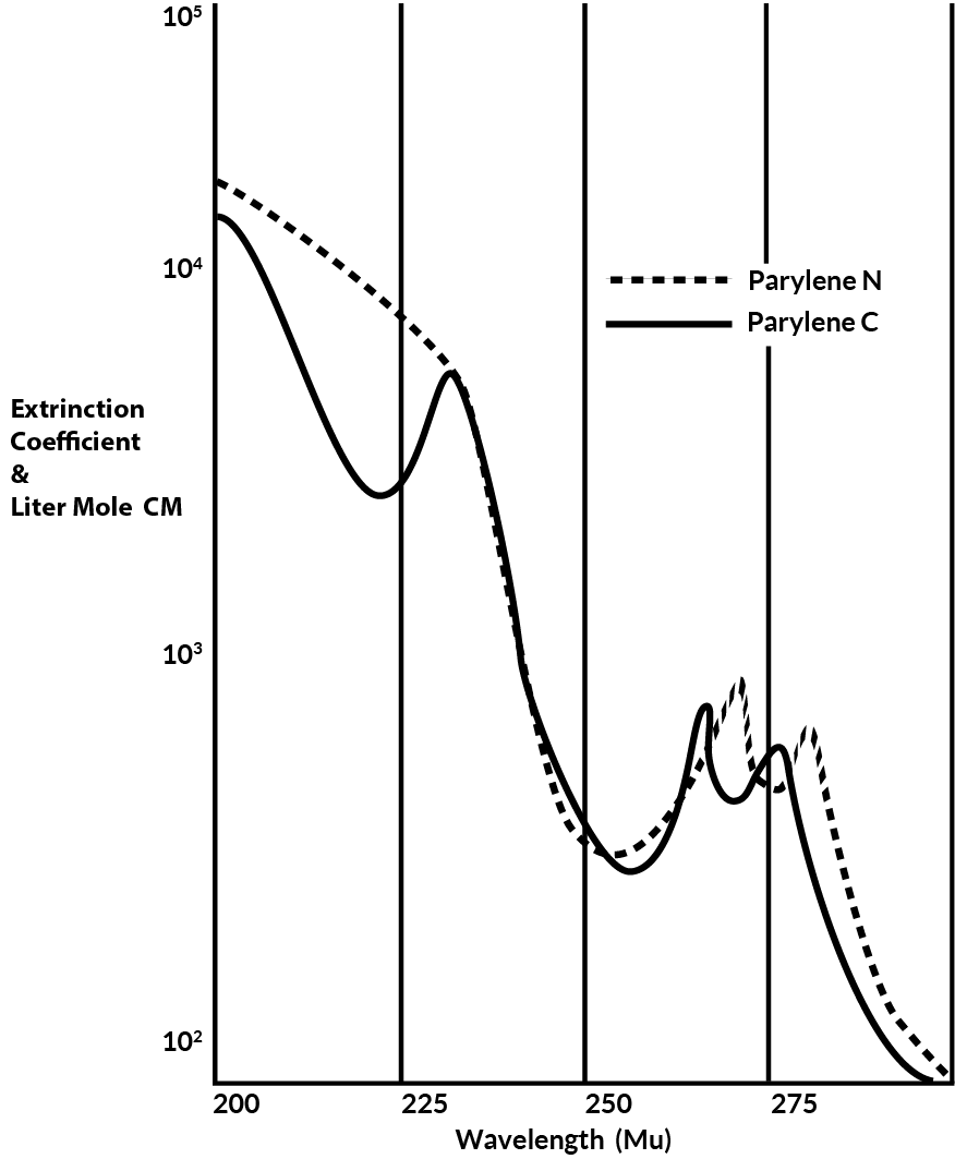
Figure 10. Ultra Violet Spectra of Parylene C & N
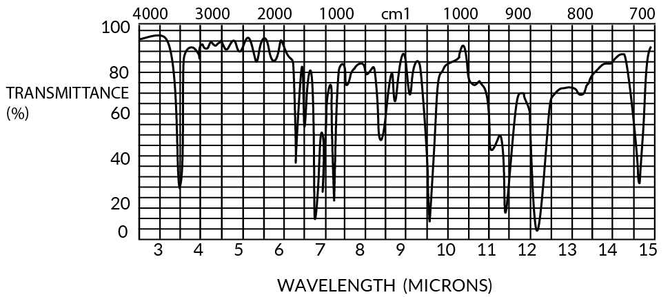
Figure 11. Infrared Spectrum of Parylene C
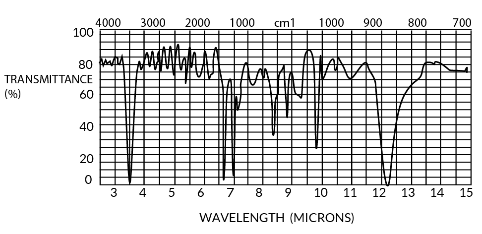
Figure 12. Infrared Spectrum of Parylene N
Chemical Resistance
The parylenes resist attack and are insoluble in all organic solvents up to 150oC. Parylene C can be dissolved in chloro-naphthalene at 175oC and parylene N is soluble at the solvent boiling, point of 265oC. Both polymers are resistant to permeation by most solvents with the exception of aromatic hydrocarbons. They also are unaffected by stress-cracking agents such as Hostepal”,”Igepal” and lemon oil.
The effect of a wide variety of organic solvents on parylenes N, C and D, was investigated.
Six classes of organic solvents were examined: Alcohol (isopropyl), ketones (acetone and 2,4- pentanedione), aliphatic hydrocarbon (iso-octane), aromatic hydrocarbon (xylene), chlorinated olefin (trichloroethylene), chlorinated aromatic (chlorobenzene and o-dichlorobenzene), heterocyclic base (pyridene), and fluorinated solvent (trichlorotrifluoroethane).
These solvents had a minor swelling effect on the parylenes with a 3% maximum increase in film thickness. The swelling was found to be completely reversible after the solvents were removed by vacuum drying.
Some inorganic reagents were also examined. These included: Deionized water; 10% solutions of sodium hydroxide and ammonium hydroxide; non-oxidizing acids, hydrochloric and sulfuric, in concentrated and 10% solutions; and oxidizing acids, nitric and chromic, concentrated and 10% solutions.
The diluted inorganic reagents had little effect on the parylenes. The acids at 10% concentrations had virtually no effect at room temperature and, except for chromic, no effect at 75oC. Concentrated acids at room temperature (23oC) had little effect. Under severe conditions, 75oC for 30 minutes, all acids had a measurable effect ranging from 0.7% swelling with hydrochloric to 8.2% with chromic. Additionally, nitric acid under these same severe conditions caused severe degradation. Both concentrated nitric and sulfuric acids caused some discoloration.
Earlier experience had indicated that parylenes N, C & D were insoluble in all common solvents. Parylene C, it was found, could be dissolved in high boiling liquids such as Xchloronaphthelene or benzoyl benzoate at temperatures above 150oC. However, these solvents are seldom encountered in the electronics industry. Of greater importance are those solvents and reagents used in processing, especially in the cleaning of components and assemblies. This study was undertaken to quantitatively measure the effect of the more common solvents and reagents on the parylenes. Included also were certain hydrocarbons serving as models for fuels. The organic liquids chosen for this study were selected as being representative of typical solvent classes. The protection provided to the coated substrates by the parylenes was also observed.
It was also known that the parylenes were inert to inorganic reagents (except for oxidizing agents). This conclusion was confirmed by the work reported here and quantitative results given.
Films of parylenes N, C, and D, between 0.5-1.5 mils in thickness, were deposited and then removed from glass plates. Removal was facilitated by applying a water-soluble release agent to the plates prior to Parylene deposition. Film thickness was measured optically by an infrared (IR) technique. Film strips were immersed in the test liquids for 90 minutes at room temperature and the thickness was re-measured by the IR method. In every case, equilibrium (no further thickness change) was reached before 90 minutes.
Results of the thickness increase as percent swelling are given in Table 13.
Slight, but measurable swelling was detected in each case, the maximum being 3% caused by O-dichlorobenzene on parylene C. (This incidentally is a solvent for parylene C removal at its boiling point of 180oC).
After measurement, immersion in the test solvent, and re-measurement, the test strips were dried overnight under vacuum at room temperature. The thickness was re-measured by the IR technique. In every case, the thickness returned to the original value.
Additional parylene strips were used for immersions in the organic solvents at elevated temperatures. The temperature chosen was either the boiling point of the solvent or 75oC, whichever was lower. Strips were immersed for 120 minutes. Again, longer immersion time did not cause further dimensional changes.
As with the tests at room temperature, slight but measurable swelling was detected in each case. The maximum swelling of 3.3% was observed with xylene (mixed) on parylene C.
When the parylene test strips were dried overnight in a vacuum, the thickness returned to the original values.
From this data, it is concluded that at temperatures under 75oC organic solvents have only a slight swelling effect on the parylenes and that this effect is completely reversible. In general, the swelling effect is most pronounced with aromatic liquids, especially chlorinated aromatics. Alcohols, aliphatic hydrocarbons, and “Freon” have the least effect.
Table 13 - Swelling or Parylene Caused by Organic Solvents
|
Solvents |
%Swelling Parlene |
|||
|
Class |
Test Member |
N |
C |
D |
|
Alcohol |
Isopropyl |
0.3 |
0.1 |
0.1 |
|
Aliphatic Hydrocarbon |
Iso-Octane |
0.2 |
0.4 |
0.3 |
|
Amines |
Pyridene |
0.2 |
0.5 |
0.5 |
|
Aromatic Hydrocarbon |
Xylene ( mixed ) |
1.4 |
2.3 |
1.1 |
|
Chlorinated Aliphatic |
Trichloroethylene ( TCE ) |
0.5 |
0.8 |
0.8 |
|
Chlorinated Aromatic |
Chlorobenzene |
1.1 |
1.5 |
1.5 |
|
Chlorinated Aromatic |
O-Dichlorobenzene |
0.2 |
3.0 |
1.8 |
|
“Freon “ |
Trichlorotrifluoroethane |
0.2 |
0.2 |
0.2 |
|
Ketone |
Acetone |
0.3 |
0.9 |
0.4 |
|
Ketone |
2,4-Pentanedione |
0.6 |
1.2 |
1.4 |
Test coupons of epoxy G-10, copper, glass, and steel were cleaned and treated for adhesion using standard techniques prior to application of a parylene coating to a thickness of 0.5 mil. One substrate of each type was tested to determine the degree of adhesion before immersing the remaining substrates in the test solutions. ASTM-D-3002-71 “Evaluation of Coatings for Plastics” was chosen for determining the degree of adhesion.
Specimens are prepared by making eleven parallel cuts, 1/16 inch apart with a razor blade, and a similar set of cuts 90 degrees to the first. 3M No. 610 tape is then pressed firmly over the cross-hatch area using a ballpoint pen eraser leaving one end of the tape free for pulling. The tape is rapidly removed using one continuous pull. The number of removed squares are counted to determine the percent failure or percent loss of adhesion. The control specimens all passed without any squares being removed.
The coated coupons of each substrate type were immersed in the solvents shown in Table 13 and were removed at intervals of 15,60,120,240 and 360 minutes. After rinsing with distilled water, the specimens were tested using the ASTM method described above.
The results of this evaluation showed that the adhesion of all three parylenes was unaffected by immersion up to six hours at both room and elevated temperatures. The appearance of the underlying substrates were unchanged by the tests indicating the parylenes are effective barriers to the solvents tested.
Parylene N, C and D films removed from glass as described above, were immersed in the reagents listed in Table 14. Thickness, by the IR method was measured after 90 minutes. Except for the oxidizing acids, equilibrium (no further thickness change) was reached before the period elapsed. Results are given in Table 14.
Slight swelling was detectable in most cases. No attempt was made to determine reversibility. Films were also tested at 75oC for 120 minutes. Under these elevated temperature conditions, there was a definite increase effect due to concentration. While the dilute solutions caused little swelling (maximum 1.2% by chromic acid on parylene N) the concentrated oxidizing acids caused severe degradation of parylenes N and C and sulfuric acid caused significant swelling of all three parylenes.
The bases caused minor but measurable swelling.
No attempt was made to determine reversibility. However, the effects of the concentrated nitric acid were obviously permanent and some sulfonation by the hot sulfuric acid would be expected.
|
Reagent |
% Swelling Parylene |
||||
|
Class |
Test Member |
Concentration |
N |
C |
D |
|
Non - Oxidizing Acid |
Hydrochloric |
10% |
0.0 |
0.0 |
0.1 |
|
Non - Oxidizing Acid |
Hydrochloric |
37% |
0.2 |
0.0 |
0.5 |
|
Non - Oxidizing Acid |
Sulfuric |
10% |
0.1 |
0.3 |
0.2 |
|
Non - Oxidizing Acid |
Sulfuric |
95-98% |
0.2 |
0.4 |
0.8 |
|
Oxidizing Acid |
Nitric |
10% |
0.1 |
0.1 |
0.2 |
|
Oxidizing Acid |
Nitric |
71% |
0.2 |
0.2 |
0.5 |
|
Oxidizing Acid |
Chromic |
10% |
0.1 |
0.1 |
0.1 |
|
Oxidizing Acid |
Chromic |
74% |
0.3 |
0.0 |
0.2 |
|
Base |
Sodium Hydroxide |
10% |
0.1 |
0.0 |
0.1 |
|
Base |
Ammonium Hydroxide |
10% |
0.3 |
0.2 |
0.1 |
|
Base |
Deionized Water |
100% |
0.0 |
0.0 |
0.0 |
Glass, epoxy G-10, copper and steel coupons were coated with 0.5 mil of a parylene after pretreatment to promote adhesion. The coupons were immersed in the test reagents and removed after 15, 60, 120, 240, and 360 minutes. The coupons were cross-hatched using the ASTM method described above. In no case, either at room temperature or at 75oC, was the adhesion of the parylenes reduced.
The appearance of the underlying substrate was observed in each case. Signs of oxidation or corrosion were noted along the cross-hatch marks for those coupons immersed in the acids but not in the areas covered by the parylene. In certain instances, after more prolonged immersion, the parylene peeled from the cross-hatched areas.
From these data, it is concluded that parylene is an effective barrier to corrosive agents.
Typical applications and uses for Parylene are listed in Tables 15 and 16.
|
Conformal Coating For Circuit Boards & Electronic Assemblies |
|
(Meets MIL-I-46058C, Type XY) |
|
Particle Immobilization |
|
(I.E. Disk Drive Metal Components) |
|
Lubricity |
|
(I.E. Catheter Guide Wires) |
|
Dielectric |
|
(I.E. Cores/Bobbins) |
|
Hydrophobic |
|
(I.E. Biomedical Tubing) |
|
Barrier |
|
(Filters, Membranes, Valves) |
|
ACCELEROMETERS |
Magnets |
|
CATHETERS |
PHOTOELECTRIC CELLS |
|
COILS |
ELECTROSURGICAL INSTRUMENTS |
|
Cores |
PLASTIC ENCAPSULATED MICROCIRCUITS (PEMS) |
|
Bobbins |
SENSORS |
|
Fiber Optic Components |
TRANSDUCERS |
|
Heat Exchangers |
CIRCUIT BOARDS |
|
Pacemakers |
HYBRID CIRCUITS |
|
Impants |
ELASTOMERIC KEYPADS |
|
Flow Meters |
Removal
Parylene can be effectively removed by three methods: Thermal, Mechanical Abrasion, and Plasma Etching. Selection of the correct method for removal is dependent upon the substrate and the area for which the Parylene is to be removed.
Due to the high melting point of Parylene, thermal removal is typically not a viable option for most products.
The mechanical abrasion method can be accomplished by either cutting/scraping of the Parylene (i.e. component removal on a PCB) or by means of micro-abrasive blasting.
The Plasma Etching method utilizes RF Plasma energy to mildly abrade the Parylene surface until it is removed. Although relatively mild, this method can also abrade or damage the substrate through generated heat, overexposure and /or oxidation.
Rework
Parylene does not adhere well to itself after completion of a deposition cycle. Therefore it is not advisable to re-coat or double coat an item that has been previously coated.
For Circuit Card Assemblies, the recommended procedure for rework is to remove Parylene only in the repair area and re-coat only the removed area with an approved coating such as Urethane or Acrylic. This should be done carefully, typically by means of a small brush. Mil-Spec allows this type of patching up to a certain percentage of total surface area.
For other types of parts, it is recommended that all of the Parylene be removed and coating reapplied.
Refer to IPC-R-700 Procedures 3.23, 3.24 and 5.5.2 for circuit card coating removal and replacement.